Original Research
Finite element study of sitting configurations to reduce sacroiliac joint loads
Isabella Bozzo1, Brandon Malz1
Published online: 27 September 2020
1McGill University, Montreal, Canada
Abstract
Low back pain can be caused by prolonged sitting, originating in the sacroiliac joint (SIJ) in up to 30% of patients. The goal of this study was to develop a finite element model of the lower back and pelvis to study sitting configurations that could minimize the loads in the SIJ while sitting. The configurations were based on chair designs with geometries known to show some benefits according to literature: a 5° downward seat pan tilt and a 20° backrest recline. Both chairs were evaluated in neutral spine position with upright posture and 30° forward leaning configurations. A finite element model of the lumbar spine, pelvis and femurs was developed to compute the reaction forces at the SIJ. The intricate spinal geometry was simplified, and isotropic material properties were assumed for all components. The chair reaction forces were first computed analytically, then inputted as loads on the model. The results demonstrate that the improved sitting configuration reduced the loads in the SIJ compared to a conventional chair in both upright and forward leaning positions by 5.57 % body weight (BW) and 14.18 %BW, respectively. The proposed sitting configuration with a downward inclined seat pan and forward leaning back was shown to be an effective method to reduce SIJ loads.
Tags: Sitting position, low back pain, finite element analysis, orthotic devices, biomechanics.
Introduction
Low back pain is commonly associated with sitting for prolonged periods of time (1). Most Canadians spend over 10 hours per day sitting, with an incidence of low back pain in as much as 75% of office workers (2,3). In 15-30% of patients with low back pain, the pain originates at the sacroiliac joint (SIJ) (4,5). The SIJ plays an important in load transfer from the upper to lower body, and stability, but it is often overlooked in low back pain assessments (3,6,7). Studying the loading response in vivo is invasive for patients so few studies have been done, leading to poor and controversial models of SIJ mechanics (19).
The optimal sitting posture was defined with the spine in a neutral position: natural cervical lordosis, thoracic kyphosis, and lumbar lordosis (8). This can be achieved by engaging the trunk muscles and stabilizing the head, so the ears are in line with the shoulders and the ribcage over the pelvis (9). This posture can only be achieved while standing, and once seated, lasts 15 minutes, with the abdominal muscles engaged at least 20% before collapsing (10). These guidelines motivated a seating configuration that maintains a braced neutral spine while sitting.
The backrest angle can strongly affect weight redistribution, which impacts disc pressure and muscle effort. By measuring the lumbar disc pressures and electromyography (EMG) output while sitting, backrest inclinations of 110° to 130° and seat pan downward inclination of 5° with continuous following lumbar support and arm rests were found to decrease both the pressure and EMG output (11). Further analysis of hip flexion angles and hip joint loading concluded that a hip flexion angle of 63.1° statically loaded the hip joint by 22.3% body weight (BW) on a standard chair, while a kneeling chair posture involved 50.2° of hip flexion and 8.7 %BW load on the hip (12). Leaning forward, i.e. hip-joint flexion, is unfavorable as it decreases the trunk-thigh angle (13). Instead triangular cushions can help to achieve a larger trunk-thigh angle of 120°, closer to the 'ideal position' of 135° (11,13,14). This position of seat pan declination increases the relative posterior tilt of the trunk with respect to the thigh. The lumbar lordosis was closer to the neutral spine curvature and led to a reduced intradiscal pressure, which minimized the risk of increasing loading that could cause low back pain.
Different features of current office chairs were compared to determine which could best reduce discomfort while sitting. Chairs with backrest mobility were compared to static backrests. Those with limited mobility backrests forced users to engage extensor muscles, resulting in higher spinal compression to remain upright (15). This worsened with slouching and improved when reclining. Most dynamic office chair models allow users to adjust the seat pan, suspension system and angle of recline. Five studies suggested no difference in trunk muscle activation, while two claimed there was greater muscle engagement, but was associated with discomfort and fatigue (16). The increased activation was attributed to the lack of a back rest. In another study, four dynamic chair models were compared to a standard office chair (17). By assessing physical activity intensity, posture and joint analysis, they concluded that the activity performed played a greater role in posture and muscle activation, with non-significant differences in sitting improvement between the models. The use of lumbar support is an important design consideration, whether it be static or feedforward continuous passive motion (CPM). A significant improvement in the visual analog scale scores for low back pain, stiffness and fatigue were measured with the use of both static and CPM support, but there was no significant statistical difference between the two (18).
Due to the invasive nature of in vivo testing of the SIJ, there is a lack of studies assessing SIJ mechanics while sitting, which has led to a poor understanding of low back pain originating at this joint (19). Therefore, there is an increasing interest to understanding the biomechanics of the SIJ while seated using finite element studies, with the ultimate aim of alleviating low back pain (19). The goal of this study was to build a finite element model that could be used to test different sitting configurations in order to determine which can lead to a reduction in the SIJ loading forces.
Methods
Improved Chair Design
Four design configurations (DC) were evaluated. The reference chair, DC 1, was built with a seat pan parallel to the ground and back rest perpendicular to the seat pan, as shown in fig. 1a. The upright position assumed direct contact of the spine with the backrest and femurs with the seat pan. The forward leaning posture, DC 2, assumed direct contact of the femurs with the seat pan with 90° of hip flexion and a 30° forward tilt of the torso, as shown in fig. 1b.
From literature, the promising characteristics for improved chairs were a 5° downward tilt of the seat pan and 20° back rest recline, which were included for DC 3, as shown in fig. 1c. A leg rest was included to support the tibia and prevent forward sliding from the downward sloping seat. DC 4, the improved chair when leaning forward 30° shown in fig. 1d, also incorporated supporting wings for the torso to prevent forward sliding. The improved seating design was contrasted to the reference chair for both the upright and forward leaning positions.
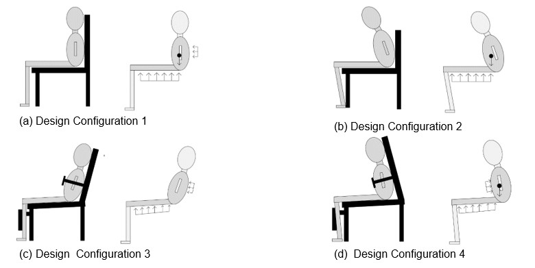
Figure 1: Free-body diagrams of the four sitting configurations, comparing the improved chair to the reference chair while seated with both upright and forward-leaning postures. (a) Design Configuration 1: Reference chair model with upright posture. Trunk-thigh angle 90°. (b) Design Configuration 2: Reference chair model with forward-leaning posture 30° from back rest. Trunk-thigh angle 60°. (c) Design Configuration 3: Improved chair model with upright posture. Reclined back rest of 20° and seat pan downward tilt of 5° from reference. Trunk-thigh angle 115°. (d) Design Configuration 4: Improved chair model with forward-leaning posture of 30°. Seat pan downward tilt of 5°. Trunk-thigh angle 65°.
Computing Reaction Forces
Anthropometric data for people in the 50th percentile, given in table 1, was used to analytically compute the reaction forces based on those shown in the free-body diagrams (FBD) in fig.1 (20). This data was used for compatibility with the model geometry obtained from the Visible Human Project BodyParts3D (21). A 3D-static FBD of the human with the chair reaction forces treated as distributed force loads was used to obtain the reaction forces. The governing equations of motion given were by a static sum of forces and moments. The model was treated as a planar problem with a stable centre of mass and rotation. The axis system is shown in fig. 2. The x-axis is perpendicular to the sagittal plane, the y-axis is perpendicular to the coronal plane in the anterior to posterior direction, and the z-axis is perpendicular to the transverse plane pointing cephalad.
| Table 1: Anthropometric data for the 50th percentile human body used to calculate the reaction forces [12]. CM: center of mass, BW: body weight. | Minimum | Maximum | Average | |
| Entire Body | Weight (kg) Length CM to Head Top (cm) |
54 65.2 |
87.9 | 70.95 |
| Head and Trunk | Weight (kg) BW Fraction (%) Length (cm) Length CM to Head Top (cm) |
30.24 54.5 76.2 43 |
50.54 61.3 87.1 53.7 |
40.39 57.9 81.65 48.35 |
| Thigh (Single) | Weight (kg)
BW Fraction (%) Length (cm) Length of CM from Trochanterion/Hip (cm) Fraction of CM from Trochanterion/Hip (%) Length of CM from Anterior Aspect (cm) Fraction of CM from Trochanterion/Hip (%) Upper Thigh Circumference (cm) Lower Thigh Circumference (cm) |
5.41
8.9 42.1 14.9 34.4 6.4 48.2 41.4 30.3 |
9.44
11.4 48.8 19 39.6 10.9 62.3 53.7 41.4 |
7.43
10.15 45.45 16.95 37 8.65 55.25 47.55 35.85 |
| Calf and Foot (Single) | Weight (kg) BW Fraction (%) |
2.91 5.2 |
5.52 6.7 |
4.22 5.95 |
The head and torso were defined as an external force in the direction of gravity on the lumbar spine. The arms and feet were not engaged with a support on the chair. When the knees were bent at 90°, the weight of the lower leg was supported by the feet in configurations 1 and 2, but not 3 and 4. The femurs were fixed parallel to the seat pan for all four configurations, and the upward reaction force of the seat pan accounted for the load of the upper body and thighs acting down on the chair. The distribution of mass from the legs and lumbar spine was assumed to be uniform and fixed to the chair. Finally, the posture was a perfectly braced neutral spine (9).
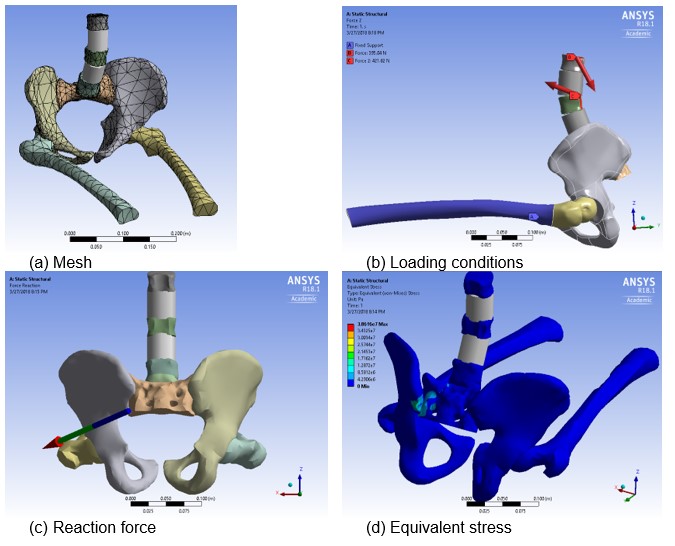
Figure 2: FEA of the SIJ with pelvic basin and lumbar spine.
Finite-Element Model
Computer aided designs (CADs) of the lumbar spine, pelvic region and femur were obtained from the BodyParts3D database, (21), and reverse engineered with SpaceClaim (ANSYS SpaceClaim, Concord, MA, USA) to obtain simplified geometries for the finite element analysis (FEA). The model was solved with ANSYS in the static structural module (ANSYS R18.1 Academic License, Canonsburg, PA, USA). The model inclusions were the lumbar spine (L1-L5 vertebrae), the lumbar intravertebral discs (IVD), the left and right innominate bone, the sacrum, and the left and right femur.
The bone and IVD were treated as a uniform body of isotropic material where Ebone = 1000 MPa, vbone = 0.45, and EIVD = 4 MPa, vIVD = 0.45 (22,23). The muscles, connective tissues, skin and organs were neglected. The resulting reaction forces were used as direct forces inputted in the FEA of the model forces, at the center of masses described in table 1, to evaluate the SIJ reaction forces. The relative loading between the model's sacrum and ilium for the four configurations was considered in evaluating the reaction forces. Nonessential complex geometries, the processes and coccyx, were eliminated, and beam contacts replaced L2 and L4 to maintain the curvature and reduce bodies and contacts.
Revolute joints were used to model the femur-hip joint contacts. Bonded contacts were used between the vertebrae and IVD. An automatic coarse adaptive mesh was applied to all the bodies, with a default element size of 0.0086 mm minimum edge length, as shown in fig. 2a. Fixed supports at the femurs recreated the static condition required to simulate sitting. The weight of the trunk was applied to the top surface of L1 as a force in the direction parallel to gravity. The analytic reaction forces of the backrest and chest wings were treated as component point forces applied to the middle vertebrae of the lumbar spine (L3) in contact with the chair, from the posterior and anterior directions respectively, as shown in fig. 2b. Through inverse dynamics, the forces within the system were solved for all four configurations at the bonded contact of the SIJ, shown in fig. 2c.
Model and FEA Assumptions
The spine was in an anatomically neutral position, ensuring a consistent spine curvature in the four positions, controlling for the spine arch variable. The relative angles between the femur and spine were constant for the upright position in both chairs, same as for the forward leaning postures. The analytic calculations for the chair reaction forces assumed a stable centre of mass and rotation in a static 3D plane. This assumed negligible autonomous movements and symmetrical mass distribution between the left and right body sides in the frontal plane. The points of application were determined for the average human, and included only the lumbar back, pelvic region and femurs, neglecting the torso, head, lower legs, and feet from the model as these were not directly in contact with the studied joints. These were represented by inputs of the FEA.
Only the lumbar vertebrae were included in the spine model, since they are the largest vertebrae supporting the total weight of the upper body. Many of the complex geometries present in the CADs of the human spine were removed or simplified as the area of interest in this study was the SIJ. Therefore, the spinous processes and coccyx would not have significantly contributed to the force distribution at this joint. An important simplification was applying the forces directly to the bone since they were the major weight bearing structures. However, the pressure developed in the muscles would exert a resultant force onto the bone equal to the applied load. This simplification made it easier to obtain the forces between the joints, as the joint reaction forces were the focus of this study.
While configuring the FEA, parameter selections were made to obtain accurate results without drastically increasing run time. Isotropic material properties were assumed for the bone and IVD (22,23). The same material properties were assumed for all the bones in the model. Treating these bodies as isotropic materials was valid for this study, as they were statically loaded, thus the strain rate was negligible. Additionally, the bone was not divided into cortical and cancellous bone, nor the IVD into the nucleus pulposus and annulus fibrosis. Treating the entire component as a uniform material was a valid assumption, since the goal was to study the relative difference in the reaction forces between the various configurations rather than quantify the magnitude of the forces The maximum equivalent Von-Mises stress was computed at the SIJ. Bone viscoelastic fracture mechanics were based on the Coulomb-Mohr theory; however, the bones were defined as isotropic materials in this FEA. Therefore, the Von-Mises stress theory was valid for this study.
The L2 and L4 vertebrae, and the connected IVD, were replaced with beam type contacts. This preserved the curved geometry of the vertebrae and IVD between the remaining vertebrae, while greatly reducing run time. The curvature was essential for even redistribution of the forces throughout the lumbar spine. The contacts between the femur and the hip bone were defined as revolute joints, with 0.01 m radius for full contact. This accounted for any possible rotation of the torso due to the applied loads at the top of the lumbar spine, from the back rest or the wings. This was a valid assumption as joints in the human body enable rotary motion, and counterbalancing forces are constantly in effect. The rest of the contacts in the system were defined as static bonded contacts. There were no joints between the vertebrae and IVD. This study evaluated a static spine while sitting, therefore, using a bonded contact for this joint was justified.
Fixed supports were used to immobilize the legs while sitting. The weight of the torso was applied normal to the surface of the L1 vertebrae since the center of mass of the torso and head occurred at approximately this point (20). The backrest and wing reaction forces were applied normal to the posterior and anterior surface of the L3, respectively. The middle of the lumbar spine was taken as the center of application of the force, as it was equally distributed over the surface of all the vertebrae and complete contact was assumed between all the surfaces. Thus, the centroid occurred at the middle vertebrae for both the backrest and the wings.
Validation
To our knowledge there are currently no in vivo or cadaveric studies directly computing the reaction forces and stresses of the SIJ in the sitting configurations described in this study. However, Van Houcke et al. (12) studied the hip-joint reaction forces (HJRF) for sitting configurations 1, 2 and 3 evaluated in the present study, shown in fig.1. In their study, the HJRFs were obtained with the AnyBody Modeling System software also using a 50th percentile male as the model (AnyBody Technology, Aalborg, Denmark). In the present study, the bones were defined as isotropic, and the femur and sacrum were in direct contact with the innominate bone without supporting ligaments or other load bearing structures. Therefore, the force exerted on the femur by the innominate bone was equal in magnitude and opposite in direction to the force exerted by the innominate bone on the sacrum, since the system was statically determinate. Hence, the magnitude of the HJRFs in the present study are equal to the those in the SIJ, making them comparable to those by Van Houcke et al.
The root-mean-square error (RMSE) was calculated between the HJRFs obtained by Van Houcke et al. and those from the FEA in this study by:
Eq. 1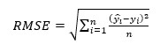
Where ŷi is the computed FEA HJRF, yi is the HJRF obtained by Van Houcke et al., and n is the sample size. This indirect validation was performed to verify the consistency of the assumptions taken in this model. The Von-Mises equivalent stress was computed to find the maximum stress at the SIJ in each scenario and again compare the chair types and sitting positions, fig. 2d.
Results
The reaction forces for each DC shown in fig.1 and the corresponding SIJ reaction forces evaluated with ANSYS are summarized in table 2. A standard chair design where the back and thighs are at 90° flexion and the feet are flat on the ground with the tibia perpendicular to the thighs, was used as the benchmark to compare the SIJ forces, as shown in fig. 1a. By comparing DC 1 to 3, a 5.57 %BW force reduction at the SIJ was achieved with the improved chair in the upright sitting position. By comparing DC 2 to 4, there was a 14.18 %BW force reduction at the SIJ while leaning forward. When looking at the two upright and forward leaning positions in the reference chair, DC 1 and 2 respectively, 4.8 %BW higher SIJ reactions were developed in the forward leaning position versus the upright one. Whereas for the improved sitting positions, DC 3 and 4, a 3.81 %BW SIJ force reduction was found when leaning forward versus sitting upright.
The maximum equivalent Von-Mises stress values at the SIJ are given in table 2. In the forward learning position, the reference chair, DC 2, had much larger stresses in the SIJ than the improved chair design, DC 4, which was consistent with the SIJ reaction forces. The stress was also reduced in the SIJ when using the improved chair, DC 3, in the upright position versus leaning forward, DC 4. However, there was a discrepancy between the two upright positions: greater stress was developed when the improved chair, DC 3, was employed compared the reference, DC 1. Despite the observed reduction in force, the smaller contact area in this position resulted in a greater stress developed in the SIJ.
The SIJ reaction forces, which were equal in magnitude to the HJRF in this FEA, are given in table 2. They were verified to ensure the system was statically determinate. The results were then indirectly validated against those obtained by Van Houcke et al., in which the HJRF were found for the first three configurations using AnyBody (12). No data exists for the fourth position. The RMSE between the HJRF for the 50th percentile human obtained in the literature and the experimental results are summarized in table 2 (12). The RMSE ranged from 19.40% to 30.25%. The maximum loading occurred for DC 2 and the minimum for DC 3. While the error was significant, the forces were in the same order of magnitude and demonstrated similar trends.
| Table 2: Analytic and FEA experimental reaction forces (R) of the four sitting configurations. | Design Configuration (DC) | 1 | 2 | 3 | 4 |
| Analytic Chair Reaction Forces | Back Rest (%BW)
Seat Base (%BW) Wing Trunk Support (%BW) |
0
77.86 NA |
0
77.86 NA |
60.58
240.16 0 |
0
240.16 65.73 |
| ANSYS Computed Experimental Reaction Forces at the SIJ | Rx (%BW)
Ry (%BW) Rz (%BW) R (%BW) |
9.03
-3.04 -30.12 31.59 |
25.29
-21.81 -14.46 36.39 |
16.69
-18.66 -7.36 26.02 |
-8.56
14.87 -14.1 22.21 |
| Simulation Experimental Results | Maximum Equivalent Von-Mises Stress at the SIJ (MPa)
Computed Magnitude of SIJ Reaction Force (%BW) |
7.79
31.59 |
75.89
36.39 |
38.62
26.02 |
28.91
22.21 |
| HJRF Validation for the 50th Percentile Human with AnyBody | Computed Magnitude of HJRF (%BW)
AnyBody Literature Value HJRF (%BW) RMSE with Van Houcke et al. (%) |
31.59
22.30 27.34 |
36.39
22.50 27.34 |
26.02
8.70 19.40 |
22.21
NA NA |
| Experimental results for the reaction force at the SIJ for all sitting scenarios corroborated with the literature values of the HJRF from (12). NA: not available, BW: body weight. | |||||
Discussion
Improved Chair Evaluation
The results obtained for the reference chair and the improved chair in the upright sitting configuration, DC 1 and 3 respectively, showed a reduction of the SI reaction forces by 5.57 %BW. This was consistent with the literature findings, which showed that a chair with a 5° declination of the seat pan and 20° recline of the backrest reduced the spinal compression and hip-joint loading (11,12). When leaning forward, the SIJ load was reduced by 14.18 %BW with the improved chair, DC 4, compared to the reference, DC 2. In both scenarios, the improved sitting configurations minimized the SI reaction forces while sitting. The relative magnitude of the reaction forces computed by the FEA were lower in the upright configurations, DC 1, versus the leaning posture, DC 2, for the reference chair by 4.8 %BW. However, the opposite was found with the improved chair that achieved a load reduction of 3.81 %BW when leaning forward, most likely due to the additional torso support from the wings.
Future Work
Further work is needed to refine the design of the improved chair. An optimization of the seat pan declination, backrest recline, and position of the wing supports along the torso should be conducted. Moreover, details in the ergonomics of the chair and material selection should be included in the FEA. Additionally, experimentation on actively returning the subject to an ideal upright position through a spring-like mechanism or prompt-feedback is warranted from the conclusion that sitting upright overall results in lower SIJ forces.
Future considerations should include using a full body CAD with advanced material properties. Also, intricate geometries of the bones, with the muscles and connective tissues, should be included. Different spine curvatures could also be modelled rather than assuming a braced neutral spine. Assessing the sensitivity of the SIJ to these parameters would help in developing an optimized chair. Furthermore, accounting for different body types is important. The study was designed using the dimensions of the 50th percentile human body. It is important acknowledge that most of the population differs from these dimensions, which can impact the outcomes.
Some important limitations of the proposed sitting configuration are patient comfort beyond the scope of the lower back. The torso support wings that were included to facilitate maintaining a neutral spine position and minimize forward leaning, placing an anterior load on the abdomen. The impact of the wings on the user and any discomfort that may arise as a result of having a retaining structure was not evaluated in this study. Similarly, the tibia supports that were included to prevent the lower legs from moving forward could cause pressure discomfort on these bones. Further, as shown by Harrison et al., a back rest recline could improve weight redistribution and reduce both disc pressure and muscle effort, however, the adverse effects on the neck and shoulder while reclined and using standard office equipment was not evaluated (11). Users may feel more strain from their head leaning forward to use office tools. These are important considerations moving forward and should be accounted for to improve comfort.
The goal of this study was to evaluate the relative improvement of the SIJ loads through different sitting configurations using a FEA. Overall, the new sitting configuration fared better than a conventional chair for reducing SIJ loads. Some limitations of the model may have resulted in higher reaction force estimates than predicted by the literature, but the relative trends were similar. For many Canadians working desk-jobs, a significant portion of the day is spent sitting; therefore, there is a need to better understand the biomechanics of sitting and develop ways to alleviate loads causing chronic low back pain.
Acknowledgements
The authors would like to thank the McGill Biomechanics research lab of Dr. Mark Driscoll, P.Eng., for the computing resources and Ibrahim El-Bojairami for his technical support.
References
- Bontrup C, Taylor WR, Fliesser M, Visscher R, Green T, Wippert PM, et al. Low back pain and its relationship with sitting behaviour among sedentary office workers. Appl Ergon. 2019 Nov 1;81:102894.
- Get Canada Standing. Active and Productive working. Sit-stand solutions. [Internet]. [cited 2020 Jul 15]. Available from: http://getcanadastanding.org/
- Joukar A, Chande RD, Carpenter RD, Lindsey DP, Erbulut DU, Yerby SA, et al. Effects on hip stress following sacroiliac joint fixation: A finite element study. JOR SPINE [Internet]. 2019 Dec 20 [cited 2020 Jul 17];2(4). Available from: https://onlinelibrary.wiley.com/doi/abs/10.1002/jsp2.1067
- Sembrano JN, Polly DW. How Often Is Low Back Pain Not Coming From the Back? Spine (Phila Pa 1976) [Internet]. 2009 Jan 1 [cited 2020 Jul 17];34(1):E27-32. Available from: http://journals.lww.com/00007632-200901010-00023
- Rashbaum RF, Ohnmeiss DD, Lindley EM, Kitchel SH, Patel V V. Sacroiliac Joint Pain and Its Treatment. Clin Spine Surg [Internet]. 2016 Mar [cited 2020 Jul 17];29(2):42-8. Available from: http://journals.lww.com/01933606-201603000-00002
- Vleeming A, Schuenke MD, Masi AT, Carreiro JE, Danneels L, Willard FH. The sacroiliac joint: an overview of its anatomy, function and potential clinical implications. J Anat [Internet]. 2012 Dec [cited 2020 Jul 17];221(6):537-67. Available from: http://doi.wiley.com/10.1111/j.1469-7580.2012.01564.x
- Kiapour A, Joukar A, Elgafy H, Erbulut DU, Agarwal AK, Goel VK. Biomechanics of the sacroiliac joint: Anatomy, function, biomechanics, sexual dimorphism, and causes of pain. Int J Spine Surg [Internet]. 2020 Feb 1 [cited 2020 Jul 17];14(Suppl 1):S3-13. Available from: /pmc/articles/PMC7041664/?report=abstract
- Broy SB, Kemmis KL. Physical Therapy, Physical Modalities, and Exercise Regimens in the Management of Osteoporosis. In: Osteoporosis: Fourth Edition. Elsevier Inc.; 2013. p. 1667-89.
- Starrett K. Becoming a Supple Leopard 2nd Edition: The Ultimate Guide to Resolving Pain, Preventing Injury, and Optimizing Atheletic Performance [Internet]. 2nd ed. Victory Belt Publishing Inc.; 2016 [cited 2020 Jul 15]. Available from: https://www.chapters.indigo.ca/en-ca/books/becoming-a-supple-leopard-2nd/9781628600834-item.html
- Claus AP, Hides JA, Moseley GL, Hodges PW. Thoracic and lumbar posture behaviour in sitting tasks and standing: Progressing the biomechanics from observations to measurements. Appl Ergon. 2016 Mar 1;53:161-8.
- Harrison DD, Harrison SO, Croft AC, Harrison DE, Troyanovich SJ. Sitting biomechanics part I: Review of the literature. J Manipulative Physiol Ther. 1999 Nov 1;22(9):594-609.
- Van Houcke J, Schouten A, Steenackers G, Vandermeulen D, Pattyn C, Audenaert EA. Computer-based estimation of the hip joint reaction force and hip flexion angle in three different sitting configurations. Appl Ergon. 2017 Sep 1;63:99-105.
- Physio Med. Correct Sitting Posture: Office. Leeds;
- Fettweis T, Onkelinx MN, Schwartz C, Demoulin C, Croisier JL, Vanderthommen M. Relevance of adding a triangular dynamic cushion on a traditional chair: A 3D-analysis of seated schoolchildren. Clin Biomech [Internet]. 2017 [cited 2020 Jul 15];49:113-8. Available from: www.elsevier.com/locate/clinbiomech
- Weston E, Le P, Marras WS. A biomechanical and physiological study of office seat and tablet device interaction. Appl Ergon. 2017 Jul 1;62:83-93.
- O'Sullivan K, O'Sullivan P, O'Keeffe M, O'Sullivan L, Dankaerts W. The effect of dynamic sitting on trunk muscle activation: A systematic review. Appl Ergon. 2013 Jul 1;44(4):628-35.
- Ellegast RP, Kraft K, Groenesteijn L, Krause F, Berger H, Vink P. Comparison of four specific dynamic office chairs with a conventional office chair: Impact upon muscle activation, physical activity and posture. Appl Ergon. 2012 Mar 1;43(2):296-307.
- Aota Y, Iizuka H, Ishige Y, Mochida T, Yoshihisa T, Uesugi M, et al. Effectiveness of a Lumbar Support Continuous Passive Motion Device in the Prevention of Low Back Pain During Prolonged Sitting. Spine (Phila Pa 1976) [Internet]. 2007 Nov [cited 2020 Jul 15];32(23):E674-7. Available from: http://journals.lww.com/00007632-200711010-00028
- Eichenseer PH, Sybert DR, Cotton JR. A Finite Element Analysis of Sacroiliac Joint Ligaments in Response to Different Loading Conditions. Spine (Phila Pa 1976) [Internet]. 2011 Oct 15 [cited 2020 Jul 20];36(22):E1446-52. Available from: http://journals.lww.com/00007632-201110150-00017
- Clauser CE. Weight, volume, and center of mass of segments of the human body. Wright-Patterson Air Force Base, Ohio; 1969.
- The National Library of Medicines Visible Human Project.
- Driscoll M. Design, Optimization, and Evaluation of a Fusionless Device to Induce Growth Modulation and Correct Spinal Curvatures in Adolescent Idiopathic Scoliosis. [Montréal]: École Polytechnique de Montréal; 2011.
- Shahar R, Zaslansky P, Barak M, Friesem AA, Currey JD, Weiner S. Anisotropic Poisson's ratio and compression modulus of cortical bone determined by speckle interferometry. J Biomech [Internet]. 2007 [cited 2020 Jul 15];40:252-64. Available from: www.elsevier.com/locate/jbiomech

This work is licensed under a Creative Commons Attribution-NonCommercial-ShareAlike 4.0 International License.